| Publication Type | Miscellaneous |
| Authors | McArthur, Donald |
| Source | (1975) |
| Keywords | tools |
Systems Approach to Video Art, Excerpted from Proposal to New York State Council on the Arts, 1975
Computer Based Video Synthesis System: Interface of LSI-11 Computer to Video Image Processing System, Excerpted from Report, 1977
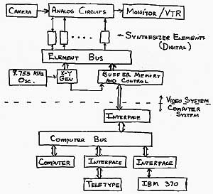
Drawing of Systems Approach to Computer/Video Interface
Systems Approach to Video Art, Excerpted from Proposal to New York State Council on the Arts, 1975
The goal of this project is the development of a system for synthesizing, processing and controlling video images with greater flexibility, reproducibility and precision than is presently possible. To extend the range available to the artist for image processing and generation, new components will be designed for the system and will include spatial and intensity digitizer, function generator, digital memory, analog to digital converter, digital to analog converter, sync generator with genlock, time base corrector and chroma keyer. The system will also consist of conventional processing devices such as colorizers, keyers and special effects generators. The processing components require control signals which can be controlled by the artist using the computer interface.
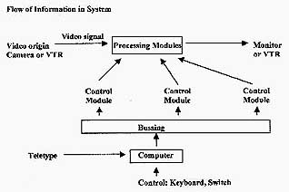
The video image is produced by an electrical signal; for a picture with fine detail the signal must be determined at time intervals of one-ten millionth of a second (100ns.). Consequently the artist must have devices which produce control signals at this rate in order to have maximum control of image production. These signals will be generated by control modules which are themselves controlled by signals from the computer. The computer processes information given to it by the artist in the form of program requests and numerical parameters. This information is analogous to a musical score. The computer behaves as an orchestra conductor in giving instructions to the control modules as required by the score but no faster than one set per frame. The control module, instrument operator, then executes the instructions producing point by point control signals for the processing modules. The processing modules correspond to the musical instruments in the orchestra.
Advantages of computer controlled systems include:
Low system cost due to economies gained by small amount of general purpose hardware.
Reliability with fewer control breakdowns.
Flexibility because set of general purpose modules behave in a specific way under computer control.
Speed
Increased control over production by artists of precise imagery.
Computer Based Video Synthesis System: Interface of LSI-11 Computer to Video Image Processing System
Excerpted from Report, 1977
Introduction
As science advances, with the resulting advances in technology. we have new tools and new capabilities which influence our world in many ways. This new technology not only influences the traditional art forms but also produces new forms of art. The development of high speed electronic components and circuits, the cathode ray tube, the video camera, and inexpensive video tape recorders enabled the development of video art. The development of small but powerful computers now allows systems to be developed which can give the video artist a new dimension of control over the video image. With a computer-based video synthesizer (CBVS), one can generate a sequence of images while controlling each individual image with detail and precision that is many orders of magnitude greater than is possible with manual control.
The ability to control the dynamics of the image is useful to the artist only if the system is capable of generating the image in real time. With this requirement in mind, the natural choice of devices for converting electrical signals to visual images is the conventional video system. This choice also gives the capability of recording the video compositions with a conventional video tape recorder and of broadcasting to a large audience through existing network systems.
There are basically two modes of operation of the system: interactive-compositional mode and automatic-production mode. In the compositional mode, the artist can enter programs and parameters through the keyboard, observe the resulting sequence of images, and then modify parameters through either the keyboard or a real time input and thus build up a data set for a complete piece. At each stage of the composition process, the data set, representing all the aesthetic decisions made by the artists, is stored in the computer. When the composition is finished the system will operate in the automatic production mode generating the final video signal in real time with no intervention by the artist. The artist may also choose to use a combination of these two modes in an interactive performance or allow an audience to interact with the system operating automatically. The system is structured so that all of these variations can be accommodated by appropriate programming.
The system may be operated as a generating synthesizer which produces a video signal entirely from internal signals or as a processing synthesizer which utilizes signals of external origin such as a video camera. Either of those two types of operations is carried out by a configurationof elements modules, each of which performs a specific class of functions, with the specific function during one frame being determined by the control paramentrs received from the computer.
The CBVS consists of two parts: the commuter section and the video. Both sections operate simultaneously and independently; communication is through the buffer memory which has a capacity of 1,024 16 bit words. Each of those words is either a picture element which controls some function of the video section and determines some aspect of one field of the video image, or it is a picture feature, a number determined by the video section and may depend on an external signal such as a video camera signal. The buffer memory is connected to the computer bus through a 16 bit parallel interface which is structured in such a way that each word in the buffer is addressable and may be read or written in exactly the same way as words in the main computer memory. Thus I/O programming is extremely simple.
During the active scan time, the control computer reads features from the buffer memory and generates elements for the following field and stores them in the buffer memory. During the vertical blanking interval, information is transferred through the element bus from the buffer to the element modules or from the feature modules to the buffer memory. The designation of a particular area of the buffer memory as an element or feature is under program control. During the transfer between the buffer memory and the element bus, the computer is locked out of the buffer memory. On completion of the transfer, the interface generates a vectored interrupt which requests the computer to generate parameters for the next field.
The computer system consists of: a DEC LSI-32 Microprocessor which has a 16 bit word length and an instruction execution time of about 7 microseconds; Teletype Keyboard and printer connected through a serial interface; 20 K of dynamic memory; a dual drive floppy disk system with a capacity of 256,256 bytes per diskette. An additional serial interface is also available for connecting through a modem to other computer systems. The entire system is dedicated to the synthesizer system.
The overall timing is determined by a 9.7552434 MHz clock which is phase locked to the subcarrier (3.57,954S MHz). This frequency is chosen to insure a coherent subcarrier and to divide the active portion of the scan line into 512 pixels. The red, green, and blue signals are generated independently, and the chroma encoding is done with analog circuits; thus there is no advantage to following the common practice of making the pixel rate an integer multiple of the subcarrier frequency. With this clock frequency, a full eight bit word is used to define the horizontal position on the active portion of the raster. The X-Y module generates 18 bits of timing information (9 bits for horizontal, including the blanking period and 9 for the line count). This module also generates sync, drive, burst flag and the TR signal which controls the timing of the buffer memory.