Every so often, you’ll see a portrait-of-the-artist documentary that’s so beautifully made, about a figure of such unique fascination, whose art is so perfectly showcased by the documentary format, that when it’s over you can’t believe the film hadn’t existed until now.
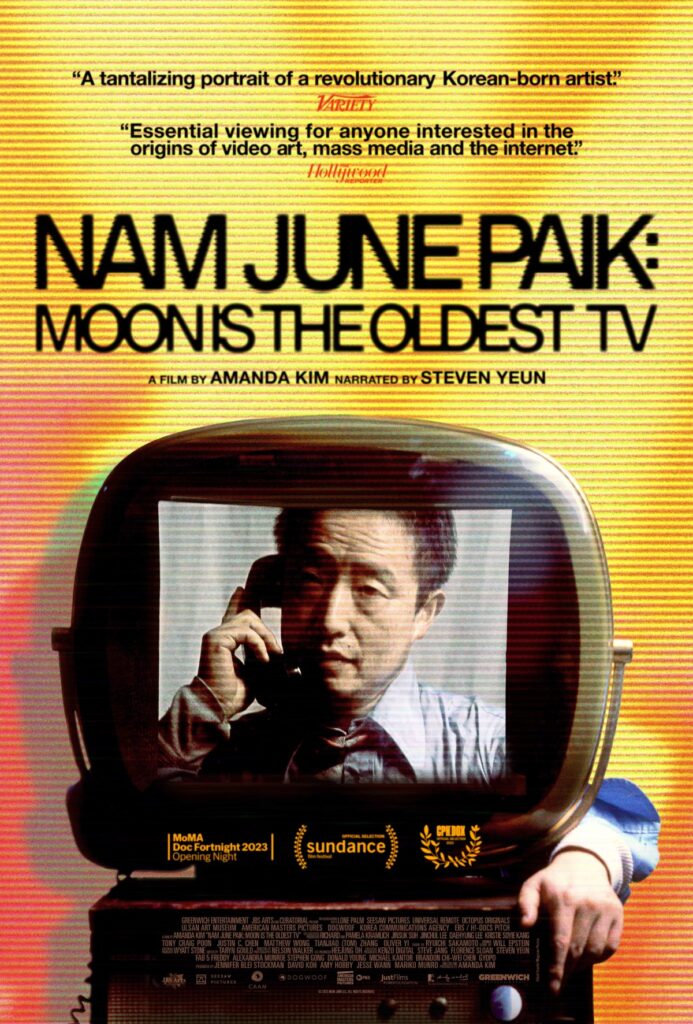
Critic’s Pick @ Variety
Experimental Television Center contributed research and archival material to the production.
Now streaming on Amazon Prime and Apple TV.
https://www.pbs.org/wnet/americanmasters/nam-june-paik-moon-is-the-oldest-tv-about-the-documentary/