| Publication Type | Unpublished |
| Authors | Sherry Miller Hocking |
| Source | (1978) |
| Keywords | tool-text |
| Abstract | unpublished manuscript used as a studio manual at the Experimental Television Center |
"The fact that TV is produced in sixth cycles is of considerable importance, because sixty cycles turns out to be the way we count time. Time again is always coming up on television. Time. Sixty cycles, sixty seconds, sixty minutes, and so on."
Les Levine, in Gregory Battcock, New Artists Video, 1978
"There is no fundamental distinction between commercial and program, there is only a difference in focus and conciseness, which gives the 30 second commercial its appearance of much greater elegance and style. Both commercials and programs are assembled out of the same syntax: the linear succession of logically independent units of nearly equal duration."
David Antin, "Videoメs Frightful Parent" 1975
In video, the image is actually an electronic signal. This video signal has two basic parts: The section containing picture information, and the section containing sync information. Synchronization is derived from the Greek syn and chronos - to be together in time; the term implies that several processes are made to occur together in time at the same rate so that they are concurrent. For a coherent picture to be formed which is easily readable to the eye and brain, the scanning motions of both the image or signal generating device, for example a camera, and the image or signal display device, the monitor, must proceed in an orderly and repeatable manner. The scanning processes in both camera and monitor must begin and end at precisely the same time. The camera and monitor must be synchronized. As the camera begins scanning the objects in front of it, the monitor begins to scan the line which the camera is scanning. As the camera ends the scan line, the monitor must also end that line. When the camera reaches the bottom of the field, the monitor must be exactly in step. Without this synchronization, the camera image and the monitor image will have no relationship to each other. Horizontal sync maintains the horizontal lines in step; without horizontal sync the picture will break up into diagonal lines. Horizontal sync tells the camera and monitor when each horizontal line begins and ends. Vertical sync also keeps the picture stable; without this, the image will roll. Vertical sync tells the camera and monitor when each field begins and ends. Both together are essential to a stable rectangular shape. Sync then can be conceived of as an electronic grid which provides horizontal and vertical orientation to the image.
Each visible line forming the raster is drawn from left to right across the CRT. Before beginning the next line, the beam must return to the left, and this return must be invisible. During this horizontal retrace period, the beam is blanked out; this process and the time interval necessary to perform this function are called horizontal blanking. Horizontal blanking is a part of synchronization.
At the end of each field the beam must return from the bottom to the top of the CRT before beginning to scan the next field. Again, this vertical retrace is not seen. This process and the interval are referred to as vertical blanking. Vertical blanking is also a part of synchronization.
Each of these blanking intervals includes information necessary to maintain proper timing relationships between camera and monitor so each begins scanning line and field at the same moment. The information which is contained in the blanking intervals is not picture information. The blanking intervals contain the timing signals which are called sync pulses. These sync pulses keep the images stable and accurate in terms of color.
Sync thus indicates a synchronization process. A number of sync pulses are required by an electronic image processing system. Normally these sync pulses are provided by a sync generator, a separate device external to the system which provides the same timing signals to each of the discrete devices within the system which need sync to operate. The single external sync generator provides identical sync signals to all of the cameras within the system.
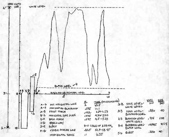
One complete horizontal line includes both the visible picture information and also horizontal blanking. Within the period of horizontal blanking the horizontal sync pulse occurs. The horizontal sync pulses occur on each line during the horizontal blanking interval and before the picture information of that line is displayed. After the beam has scanned one line, the beam is blanked out in preparation for the next scan; it is during this interval that the horizontal sync pulses are inserted. They insure that the line just scanned by the camera can be accurately reproduced by the monitor and tell the monitor when each line is to be scanned. One complete horizontal line is scanned in 63.5 microseconds, or .0000635 seconds. The visible picture portion of this line takes approximately 52.7 microseconds. The remaining time, 10.8 microseconds, is the horizontal blanking period. The blanking period consists of the front porch section which is approximately 1.27 microseconds, the horizontal sync pulse and the back porch section each of which are approximately 4.76 microseconds. The back porch is approximately 3.5 times as long as the front porch.
The vertical sync pulses occur within the blanking interval at the beginning of each field. The first 21 lines of each field consist only of timing information. They do not contain any picture information. They are collectively known as vertical blanking. The following 241.5 lines of the CRT are scanned, and then the beam has traced all of the picture lines. The period of time it takes for the beam to return to the top after each field is scanned is called vertical blanking, approximately 1330 microseconds long, much longer than horizontal blanking.
The first series of pulses to occur during the blanking interval are six equalization pulses. These are followed by the vertical sync pulse serrations, which are followed by another series of six equalization pulses. The duration of each set of pulses or three horizontal lines, is abbreviated 3H. The frequency of the equalization pulses is twice the horizontal frequency. These equalization pulses help to maintain the interlace between fields and also help to keep the oscillators which control the horizontal scanning in step during the time in which no lines are being scanned. The equalization pulses insure that the vertical deflection occurs at the same time as vertical sync. They also keep the horizontal deflection in step.
The vertical sync controls the field-by-field scanning process performed by the electron beam and also maintains the horizontal oscillator in step. The function of the vertical sync pulses is to indicate to the monitor when each field has ended so that the camera and monitor begin and end each field in direct relationship to each other.
The vertical serration pulses help maintain proper horizontal frequency during the vertical interval. The frequency of the serration pulses is twice the horizontal frequency.
The horizontal sync pulses which conclude the vertical blanking interval also help to keep the horizontal oscillator in step during retrace.
In order to achieve interlaced scanning, each field contains a half line of picture information. The line preceding the vertical interval of the odd field is one complete picture line. This line is the last line scanned in the even field. The vertical interval, occupying 21 H lines, then follows. The first picture line of the odd field which follows the vertical interval is one full picture line. 241.5 picture lines follow. The 21 lines of the vertical interval and the 241.5 lines of the picture information total the 262.5 lines needed for one field. The last 1 /2 picture line of the odd field then immediately precedes the vertical interval for the even field.
The odd field, as noted, is preceded by one complete picture line, the last in the even field. The vertical interval for the odd field begins with six equalization pulses occupying 3H. Six serration pulses follow, also occupying 3H lines. After the next six equalization pulses, the horizontal sync pulses occur. The first of these occupies 1/2 line. It is here, in part that the off-set relationship occurs which provides for interlaced scanning. Eight to twelve horizontal sync pulses without picture information conclude the vertical interval. Following the 21st line of the vertical interval is the first picture line of the odd field, a complete horizontal line. The odd field scans 241 complete horizontal picture lines and ends with 1/2 picture lines.
This ½ picture line immediately precedes the vertical interval of the even field. The equalization and serration pulses of this field possess the same timing relationships as those of the odd. There is no off-set present.
The vertical blanking period under broadcast conditions contains two additional signals which are used far reference and testing. The first, called the Vertical Interval Reference or VIR signal, is added to line 19 of both fields to maintain the quality of the color transmitted. Certain color receivers are now made which use this signal to automatically adjust hue or color and saturation. The second signal, called the Vertical Interval Test, or VIT signal, is used as a test signal to evaluate the performance of equipment and appears on lines 17 and 18. Other information can be coded into the vertical blanking interval, including program subtitles for hearing impaired individuals. The captions, provided in 1980 by several of the networks and PBS, appear on the screen as text when used with user-purchased decoders. Other systems can provide data such as weather, sports and news reports.
Sync and drive pulses are the timing pulses which keep one or several cameras in step with each other and with the videotape recorder or monitor. In a single camera system, sync can be obtained from the internal sync generator built into the camera. The -video and sync information together are then sent to the deck or the monitor. In a multiple camera system, the internal sync generator in each of the cameras cannot be used to send timing information to the rest of the system. All cameras must receive the same sync signals from a common source at the same time, from a sync generator external to all of the cameras. Video or picture signals from all the cameras are then mixed in the processing system and combined with sync information. This single composite signal, containing both picture and sync information, is sent to the deck to be recorded.
A black and white sync generator usually supplies horizontal and vertical drive pulses, composite blanking which includes both horizontal and vertical blanking, and composite sync which also includes horizontal and vertical components. The function of the sync pulses is to indicate to the camera or monitor when one line, in the case of horizontal sync, or one field in the case of vertical sync, will end and the next begin. The blanking pulses make sure that the retraces, both horizontal and vertical, are not visible. Drive pulses control the timing of the beamメs scan.
The color sync generator supplies horizontal and vertical drive, composite sync and composite blanking and two additional signals variously called burst or burst flag and subcarrier or 3.58 MHz. Color signals must carry all color information, including the hue, brightness and saturation of the colors, by the use of three primary colors: red, green, and blue. In addition, their structure must be such that they are compatible with black and white systems. A color signal must play on a black and white television with no interference. Color signals must therefore contain both luminance and chrominance information. Luminance conveys the variations of light intensity and is the part of the signal used by the black and white monitor. Chrominance conveys variations of hue, saturation, and brightness.
The subcarrier signal, with a frequency of approximately 3.58 MHz, carries information about color value. This frequency is produced by an oscillator in the sync generator, and is modulated or changed by the color information coming from the color camera to the colorizer in the image processing system. The ways in which the subcarrier is changed convey information about the color, its saturation and hue. For example, changes in the phase of the chrominance signal indicate changes in hue.
In order that changes in phase, for example, and the resulting changes in hue can be identified, a reference signal is required. The burst signal supplies 8 to 10 cycles of the 3.58 MHz subcarrier frequency without any color information. This serves as a reference point to establish the phase relationship of the subcarrier signal before it is modulated and starts to carry color information. The burst signal is located on the back porch of each horizontal blanking pulse. It is not present after the equalization or vertical pulses of the vertical interval. The average voltage of the color burst signal is equal to the voltage of the sync signal. Burst then helps to synchronize color.
The horizontal drive signal occurs at the rate of 15, 750 Hz. Its duration is 1 / 10th of the time it takes from the beginning of one horizontal line to the beginning of the next, or about 63.6 microseconds. Vertical drive occurs at the rate of 60Hz and lasts for about 666 microseconds. Both pulses are sent to the cameras to control horizontal and vertical deflection circuitry, that which dictates the scanning processes.
Horizontal and vertical blanking pulses are pulses which make invisible the retrace lines which occur as a line or field is ended and the beam returns to begin the next trace. Vertical blanking lasts about 1330 microseconds and horizontal blanking about 1 microseconds. Composite blanking with the addition of the video signal is sent to the monitor to blank out the vertical and horizontal retraces. The camera usually is not supplied with vertical and horizontal blanking because the horizontal and vertical drive pulses can accomplish the same function. It is during the blanking intervals that horizontal and vertical sync occur. Horizontal blanking and horizontal drive control the direction and speed of each of the beamメs horizontal traces and retraces. Vertical blanking and vertical drive control the change from one field to the next.
The sync signals tell the camera or monitor when the scan is to change. Horizontal sync controls the beginning and end of each horizontal line. Vertical sync controls the beginning and end of each field. It assists in keeping the monitor in step or in sync with the camera. In a multiple camera system it also keeps all cameras synchronized with each other. Some cameras use sync rather than drive signals to produce the deflection signals which control the beamメs scanning processes.
Line frequency, or 15, 750 Hz, is produced in the camera and monitor by crystals which oscillate or vibrate naturally at the speed of 31, 500 Hz. This rate is then divided in half electronically to produce the required 15,750 Hz frequency.
The field frequency of 60 Hz can be derived by dividing the line frequency by the number of lines (525). These pulses can then be sent to the horizontal and vertical deflection circuits of camera and monitor to insure proper scanning.
Line and field time base stability refer to the precision at which the line and field frequencies operate. Exact operation is essential to the operation of the system as a whole and compatibility between output signals from different systems. The stability of the time base found in small-format recording can be corrected through the use of a time base corrector.
If the signal sent from the camera to the monitor includes picture information, horizontal sync, horizontal blanking, vertical sync, and vertical blanking, then the signal is called a composite black and white video signal. If the sync information is not included in the signal sent from the camera, this signal is called a non-composite video signal.
In a single camera system, the sync generator inside the camera may be used to generate the necessary sync information for recording and display. In this instance, the camera is usually referred to as being on internal sync, and the composite video signal is sent to the recorder or monitor. A single camera system may also be used with a sync generator which is external to the camera. In this case, the external sync generator generates the sync information which is then sent to the camera. The camera in this case is on external sync. Some cameras can operate on either internal or external sync. There is a switch on the camera for selecting the sync option. Many cameras only operate on internal sync. These cameras cannot be used in multiple camera systems. Whether internally or externally locked, signals are produced which drive the deflection systems of the camera and insert the waveform onto the video out signal which causes the monitor to be in sync with the camera.
In a multiple camera system, such as an image processing system, the sync information for all cameras must come from one common source. In a multiple camera system, each of the cameras is sending picture information which will eventually be combined and treated by a variety of image processing devices. Techniques such as mixing, switching, or keying can be employed. None of the cameras in the system is generating its own sync information. A common sync source is sending identical sync information to each of the cameras in the system. The camera then sends back to the system a composite video signal containing both picture and sync. If each of the cameras in the system were to generate its own sync, there would be no consistent timing information throughout the system. It would then be impossible to achieve a stable image. In an image processing system the sync generator which sends sync to all of the cameras is usually external to each of the other components in the system. One common source sends the same information to each of the cameras.
The monitor or deck receives a composite video signal from the system which includes: picture information, horizontal and vertical blanking, horizontal and vertical drive, and horizontal and vertical sync as well as the signals needed for color. The blanking, drive and sync information are used to control the deflection of the scanning beam, so that the image displayed is a stable and faithful representation of the camera images.
The sync generator then serves as a master clock which establishes the time frames for the signals which, when decoded, produce images. The sync generator insures that the scan and retrace processes for both horizontal and vertical in both camera and monitor occur at the same intervals with respect to video. The sync generator also provides blanking signals, both horizontal and vertical, which are added to the video waveforms. If the sync generator also supplies timing signals to drive the deflection systems of camera and monitor which then maintains the phase relationships between horizontal and vertical scanning, the 2:1 interlaced scanning is achieved. If 2:1 interlaced scanning is not present, the sync is termed "industrial" or random.
If the horizontal and vertical signals are not locked together in phase but are derived independently, then random interlace scanning results. In this type of scanning, the horizontal lines in each field are not in any fixed position and are not evenly spaced. Occasionally because of this lack of even horizontal positioning, horizontal lines maybe traced on top of each other. This results in the lass of picture information contained in the superimposed lines and a degradation of the picture. This is called line pairing.
During the vertical sync period, it is necessary that horizontal information be supplied or the horizontal oscillator in the monitor may drift. The frequency corrections to that oscillator which are then needed following the vertical sync period may cause flagging at the top of the image. Flagging appears as a bend toward the left or right in the first several lines of the image.
Standardized sync signals are necessary to insure compatibility and interchangability. The Electronic Industries Association, EIA, has developed standard configurations for the synchronizing waveforms in video systems, RS-170. RS-170 requires sync, composite blanking, vertical drive and horizontal drive signals.