| Publication Type | Miscellaneous |
| Authors | Sherry Miller Hocking |
| Source | (1986) |
| Keywords | tools |
Antecedents and Description
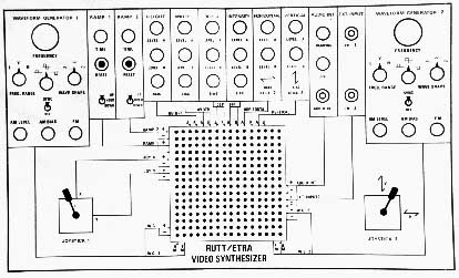
Block Diagram of the Rutt/Etra
The Rutt/Etra
Antecedents
Bill Etra used the Paik raster manipulation device at the TV Lab at WNET in NYC about 1971. Etra then constructed his own, based only on his observations and use of the tool. This unit was eventually used by Barbara Buckner. Etra had also seen video works by Walter Wright and Ed Emschwiller, produced at Dolphin Studios. The Scanimate, and later the Caesar system, were powerful imaging tools used at Computer Image Corporation for commercial applications and were generally inaccessible to media artists at the time.
Steve Rutt had been working with commercial applications of strobe technology, and had access through Etra to ½" video recording equipment; Rutt was interested in the time-based nature of the medium. Etra showed Paik's device to Rutt, and invited him to collaborate on the design of a new imaging machine.
Etra wanted a system which allowed for zoom and pan, wherein the image could be reduced in size. He and Steve Rutt wanted to rectify what they perceived as a limitation of Paik's design, the fact that the raster device was AC coupled. DC coupling would allow for positional movement, rather than distortion of the waveform, which was how the Paik unit operated.
With support from the New York State Council on the Arts to the TV Lab in 1972-1973 and with considerable personal investment the prototype was developed. The machine was later commercially developed.
The original machine, as described by Etra, was constructed on an oscilloscope. Prior to the commercial machines, the R/E was not modular in construction. It had a less sharp CRT, with no control over the intensity of the display with the same speed as the control over other functions. The scan was non-linear, and there was no dual-trace.
The R/E then began as a modified and improved raster manipulation system. In contrast to Paik's device, the R/E was modularized, and packaged into rack-mountable units. It was constructed from standard, commercially available parts rather than surplus components. The design was documented. Probably the most significant design concept was the fact that the device was DC coupled. This permitted positional movement; the image could be positioned in a particular place on the raster, and it could be flipped upside down. The R/E provided a sharper resolution CRT and was voltage controlled.
The important contribution of the Rutt/Etra was in the concept of retiming of the image frame relative to the incoming sync. As Bill Etra indicated, "The Rutt/Etra changes the time in which you see parts of the picture. It is a machine that manipulates images in time."
The standard modules consisted of waveform generators, summing amplifier, and ramp generator. The ramp programmer was optional, allowing the user to do more than one move. The Joystick X, Y, Z controlled was also an option; it was a manual interface which could be assigned to control other devices. The output was engineered to provide smooth motion. The R/E also has Diode Modules and an Audio Interface.
The system was marketed both to individual media artists as well as broadcast and production facilities. The machines were labor-intensive to produce and therefore expensive to build. The cost increased because the effort to keep the price low, and therefore accessible to individuals, was predicated on increased volume which didn't materialize. Etra cites a lack of creative interest on the parts of the production facilities which couldn't envision creative applications for the unit.
The system also had several technical flaws. The waveform generators never worked to full capacity, and the CRT was easily burned, requiring replacement.
Description
The Rutt/Etra Scan Processor was an analog system which allowed the user to manipulate the deflection signals in real time to created the video image. It was designed and built by Steve Rutt and Bill Etra in the early 1970s.
The system was contained in three units. The first consists of a black and white monitor display with special yokes for the deflection, as well as a video amplifier. The second contained control voltage generators, ramp generator and summing amplifier. The last box contained the sweep processing.
The unit allowed the operator to directly modulate the sweep signals of the monitor with various control voltages. The resulting images were re-scanned, that is, a video camera was pointed at the monitor and the resulting images were recorded.