| Publication Type | Miscellaneous |
| Authors | Sherry Miller Hocking; Brewster, Richard; Peer Bode; Hank Rudolph; Matthew Schlanger |
| Source | (1980) |
| Keywords | tools |
Jones Keyers I and II
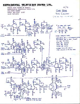
There are two Jones Keyers located in the case with the Sequencer, and they both function in the same way. Figure I shows the front panel controls of the keyers. Both are hard-edge, luminance keyers. The clip input can either be routed from one of the two main channel inputs for internal keying or from a third and separate source for external keying. This is determined by a three-position clip select switch (5). Each of the two main channels is a VCA with separate gain (6) and pedestal (7) control knobs. The clip channel has a clip level control knob (3) which determines at what gray level the transition between channel A and channel B will take place. There is also a two-position switch to allow you to use or by-pass the clip (1) and a switch for normal and reverse keying (2). All of the parameters except the clip input select are voltage controllable. The modules are designed to accept plus/minus 5 volt signals with frequencies up to several multiples of the horizontal line rate. The voltage control input (4) for the clip level has a built-in attenuator for adjusting the range of the wipe. All of the knobs will bias the associated incoming control voltage.
How to Use the Jones Keyer
1. Select the channel inputs at the matrix.
2. Set the on/off control (1) to the down or off position. In this mode the clip input is by-passed and the normal/reverse control (2) acts as a two-input switcher which is either manual or voltage controllable.
3. Set the N/R control (2) to the up or normal position. This will present the input signal of channel A to the output.
4. Adjust the gain (6) and pedestal (7) control knobs on channel A for the desired range.
5. Set N/R control to the down or reverse position. This will present the input signal of channel B to the output.
6. Adjust the gain and pedestal control knobs on channel B.
7. Select the clip input (5). For internal key, choose position A or B. For external key, select the input at the matrix and also set the clip input select switch to C
8. Set the on/off switch to on. 9. Set the N/R switch to normal.
10. Adjust the clip level control knob.
Jones Keyer III
This is a hand-wired prototype. Its functions are similar to the other keyers, except the front panels are arranged differently. All the VC inputs are on the left. Jacks marked "G" and "P" 1 are the VC inputs for the gain and pedestal of Ch. A "C" is the VC input for the clip level etc. There are no builtin attenuators for the VC input of the clip, as with Keyers I and II.
Keyers IV and V
These are also 3 input voltage-controllable luminance keyers. They differ from the others in the following ways:
1. There is no clip, select bus. The signal input to Ch. C of that keyer on the matrix is the clip input. The signal acting as the clip input must be routed to Ch. C as well as into one of the VCA channels with the second signal into the remaining channel, even for internal keying.
2. There are no separate pedestal controls for each channel. The BAL control determines the relative pedestal levels of the two VCA channel inputs.
3. The key On/Off and key Normal/Reverse controls are only manual; they are not voltage controllable.
There are separate gain controls for each VCA channel and a clip level control for the clip channel. Along with the balance, these are voltage controllable. There are no built-in attenuators for the VC inputs.
Jones Keyer documentation by Richard Brewster, c 1976